
APFCR Panels
We provide solutions. All our work is focused around the client's needs.
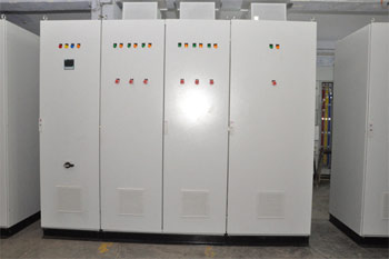
APFCR Panels
Available in Two designs. With Contactor base circuit & with Thyristor switches. Air ventilation for Capacitor banks, Auto Manual facility. Designed to control smallest capacitor upto 5 kvar.
GENERAL SPECIFICATIONS-POWER CAPACITOR EQUIPMENT CONSTRUCTION
1. The power capacitor are self-healing; metallised Polypropelene (MPP) type and completely resin moulded in hermetically sealed containers, naturally cooled, indoor type. PFC back are contactor based.
2. Capacitors are designed, manufactured constructed and tested in accordance with relevant code.
3. The power losses does not exceed 0.2 Watt / KVAR (or 0.4 watt / KVAR taking the discharge resistance into account).
4. Every capacitor equipment are provided with a directly discharge device providing a discharge path without having a disconnecting switch, fuse cut-out, or series capacitor interposed.
5. The discharge device reduces the residual voltage from the crest value of 660 volts to 50 volts or less within one minute after the capacitor disconnected from the source of supply.
6. Facilities are provided for short-circuiting the capacitor terminals together and to earth before handling.
7. When capacitors are switched off and on at very short intervals, arrangements are made so that, at the time of reapplication of the voltage, the voltage at the terminals of the capacitor are not more than 10% of the rated r.m.s. Voltage.
8. Each unit of capacitance are a 3 phase balanced load and controlled by a adequately rated triple pole contactor.
9. Each bank of capacitor units are provided with an incoming bus bar chamber rated for the total load of the maximum number of capacitor units. Units are interconnected by an enclosed all insulated Aluminium/ bus bar system.
10. Each unit of capacitance in a bank are provided with a red pilot light to indicate when the capacitor is operational.
11. Acceptable, harmonic current handling capacity (for p=7% de-tuned reactor):
11.1. I1 = 1.06 Ic ( fundamental current )
11.2. I3 = 1.04 x I1 (3rd harmonic)
11.3. I5 = 1.31 x I1 (5th harmonic)
11.4. I7 = 1.13 x I1 ( 7th harmonic)
11.5. I max =1.5 x I
PROTECTION AND AUTOMATIC CONTROL
1. A main circuit breaker complete with spring operated mechanism and operator independent is provided as the main protection for the automatic power factor correction equipment.
2. All switching and protective devices and the connections are designed to carry continuously a current of 1.3 times the current, @ rated AC voltage and Frequency
3. An electronic reactive volt-ampere regulator will switch automatically on the required number of blocks according to load, so as to maintain the power factor at the set value indicated by the reactive power regulator. The regulator controls the opening and closing of the capacitor switching contactors. The range of the regulator is 0.8 to 0.99.
4. Each contactor capacitor assembly is referred to as a capacitor step. The number of capacitor steps of switching operation is as per single line diagram.
5. Each regulator is equipped with a device that automatically disconnects all connected capacitors in the event of a power failure. When power is restored, the capacitors are re- connected according to system reactive power needs, avoiding excessive capacitive power.
6. An overload relay is fitted to trip the main incoming circuit breaker to the capacitor bank, and an out-of-balance current relay included to give visual / audible warning.
7. Fail safe feature is incorporated to prevent leading power factor from every occurring.
8. All contactors and switching devices is suitable for capacitor switching and is designed such that re striking during breaking operation cannot occur and heavy inrush current shall not cause contact welding during making operation.
9. Local Display: LED or liquid-crystal digital type, mounted in door of enclosure, indicating the following:
9.1. Target and actual power factors accurate to plus or minus 1 percent of reading.
9.2. Steps energized.
9.3. Step reconnection delay.
9.4. Real and reactive currents.
9.5. Voltage total harmonic distortion.
9.6. Alarm codes.
9.7. System Alarms: Alarm relay and local display indication of the following conditions:
9.8. Low power factor.
9.9. Leading power factor.
9.10. Frequency not detected.
9.11. Overcurrent.
9.12. Overvoltage.
9.13. Over temperature.
9.14. Excessive voltage total harmonic distortion.
9.15. Capacitor overload.
9.16. Loss of capacitance.
10. Communication module -Optional
CUBICL
1. A cubicle is provided with
1.1. Main incoming circuit breaker / SFU complete with external operating handle complete with padlocking facilities
1.2. Contactors and Thyristor, protective and regulating devices.
1.3. Connecting terminals for testing of circuits.
1.4. Status indication lamps showing switching operation of each capacitor bank. Illuminated pushbuttons is of clustered LED type with Short Circuit protection, Surge Protection etc.
1.5. Adequately rated CTs and PTs
1.6. Ammeter, Voltmeter and Power factor meter.
1.7. Anti-condensation heaters of standard make complete with thermostatic control.
INTERNAL WIRING
1. Control panel is complete with all internal wiring and ready for Purchaser's external cable connections at the outgoing terminals. All inter-modular wiring within the control panel for control and interlock looping is carried out by the control panel supplier.
2. All wiring inside the control panel is carried out with 1000/600 V grade FR-LSH / Nywin insulated wires having moisture resistant properties.
3. All control wiring except CT secondary wiring is carried out with minimum 1.5 sq. mm copper conductor. CT secondary wiring is carried out with 2.5 sq. mm. Copper conductor.
4. All terminal blocks and wires is tagged for identification in accordance with BS EN 60439.
5.All wiring for external connections is brought out to the individual terminals on a readily accessible terminal block. All terminal blocks is shrouded or provided with transparent covers.
6. Clamp type control terminal blocks is provided for outgoing control cables. Minimum 10% or 4 nos. spare terminals is provided for future use. Control terminal block is separated from power terminal blocks by means of an insulating barrier.
Flexible cables is used for wiring to equipment on doors and is so arranged that it does not get trapped during door movement.